

|
Are
you really getting the power you think you're getting?
|
||
|
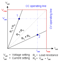
Maintaining constant voltage or constant current In constant voltage (CV) mode, a supply adjusts its output current as needed to maintain the output voltage you set. This feature compensates for variations in the load resistance to make sure you get the voltage level you need without constantly monitoring and adjusting the supply output.
Constant current (CC) mode works the same way: the supply adjusts Vout along the CC operating line as needed to maintain Iset. (At operating point 2, the supply is in CC mode.) If you have a java enabled browser try our interactive demonstration of the graph to the right.
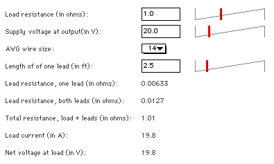
Limiting output levels CV and CC modes can't operate over unlimited ranges, of course. To protect your circuit and stay within the supply's operating range, CV mode works in tandem with a feature called current limiting. CC mode has a corollary feature called voltage limiting. You enable current limiting in CV mode by setting a current level (Iset) after you've set the desired voltage level. The supply adjusts the current as much as it can to maintain Vset. As long as the load resistance (RL) is greater than the ratio of Vset to Iset (RC), the supply stays in CV mode and adjusts Iout as needed. When RL drops below RC, however, the supply switches to CC mode to avoid excessive current through the load. Instead of adjusting Iout, the supply now adjusts Vout as needed to maintain Iset. Voltage limiting in CC mode works the same way. Bear in mind that it is possible for a supply to briefly enter states where neither CV or CC applies, leaving the output unregulated. This can happen during the switchover from CC to CV and vice versa, for instance. Compensating for lead resistance Once you've made all the necessary allowances for the load, you might also need to compensate for voltage drops across the leads you're using to deliver power to the load. In most cases, lead resistance won't be a major issue, but a combination of small-gauge wire, long leads and low load resistances can have significant effects. This voltage loss calculator will give you an idea of how much trouble a set of leads can cause. First select a wire size (this assumes copper wire). Then set the load resistance, voltage at the output of the supply, and the length of one lead (in feet). If you have a java enabled browser try our interactive demonstration of the graph below.
Net voltage at load shows the voltage actually delivered to the load. The power supply may be doing a great job of regulating the output, but it's sensing the voltage at its own output terminals, not at the load.
To minimize noise effects, use twisted two-wire shielded cable for the sense leads. Connect one end of the shield to ground and leave the other end unconnected. Also, review the remote sensing specifications for your particular supply. Remote sensing can have a modest effect on the supply's output regulation.
|
||


 The
solution to this problem is a feature called remote sensing. Using
another pair of leads, you let the supply read the voltage at
the load, and it can then compensate for the voltage loss across
the leads (and connectors, relays, and anything else you stick
between the supply and the load).