

| Measurement
performance in data acquisition systems: How much is enough? 
|
|||||||||||||||||||||||||||||||
|
On the upside, you can find an answer for practically every application and every budget. On the downside, your hair could turn gray(er) by the time you sort through the hundreds of solutions out there to find the right one for your needs. Fortunately, you can narrow the decision process down to just five key attributes:
This
article explores measurement performance, the attribute most likely
to cause confusion when it comes to buying and applying a data
acquisition system.
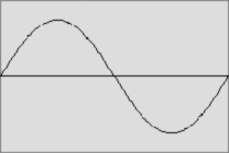
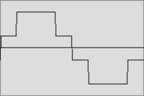
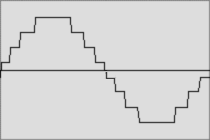
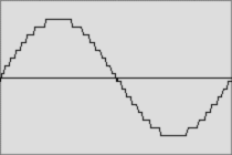
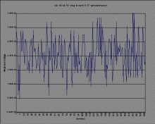
To an extent, you can live with low resolution by shifting the input range to focus the available resolution on a narrower amplitude range. However, higher resolution lets you measure a broader range of amplitudes without changing the input range, which can slow measurements, add settling errors, and in some cases even require hardware modifications or different signal conditioning. Noise Noise is reflected in the stability from reading to reading, or the repeatability of a measurement. It is sufficiently large in some systems that it dominates the overall measurement accuracy. Noise enters data acquisition systems a number of ways; one common path is through noisy instrument environments. PC plug-in cards are at a disadvantage here because inside the PC they are exposed to high-frequency processor and bus signals that couple into measurements and can seriously degrade performance. In recent years PC card vendors have addressed this problem with shielding and thoughtful board lay-outs, improving noise performance immensely. However, standalone data acquisition systems, such as VXI, still have an advantage because they are removed from the noisy PC environment and carefully designed to minimise internal noise (Figure 2). If you have a java enabled browser try our Interactive Noise Application of the screens below.
Note: The HP 34970A and the PC plug-in card (a popular 16-bit model) were set up as identically as possibly. The HP 34970A was configured with the HP 34902A 16-channel reed multiplexer. Both systems were set to dc volts on the 0-100 mV range. The short was placed directly on the terminal block on the HP 34970A and directly on the PC card connector. A second noise path is through the cabling you use to connect your transducers. Troublesome 50/60 Hz noise couples into cabling from surrounding power cords and wiring, lights and other electrical equipment. While much of this noise can be avoided with proper cabling (by using shielded twisted pairs, for example), some power-line noise still finds its way into the ADC. Data acquisition systems use a variety of means used to reject this noise:
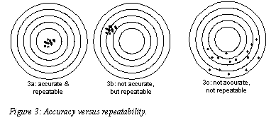
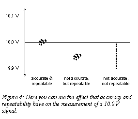
Accuracy Accuracy reflects how closely the measured value matches the actual value of a signal. For example, a data acquisition system with 0.1% system accuracy will measure a "perfect" 10 Volt source with up to 0.1% of error; it might display as high as 10.01 V or as low as 9.99 V. Clearly, the better the accuracy, the better the quality of the data, and the more confidence you can place in your results. Figure 3 compares the concepts of accuracy and repeatability, and Figure 4 demonstrates how the three possibilities would affect an actual measurement.
If you have a java enabled browser try our Interactive Accuracy Application of the screen above.
Comparing
accuracy specifications of data acquisition systems is not always
as easy as reading numbers right off the data sheet. There are
many sources of error in a data acquisition system and thus many
accuracy figures to consider, including the following:
Some manufacturers simplify the exercise by providing "system" accuracy specifications, which combine all these instrument-generated errors together into a single number. Others list each accuracy component separately, and you must carefully add them to come up with the final performance number. When comparing data acquisition system specifications, make sure you compare overall system performance. Also, you'll need to add the transducer error to determine complete measurement accuracy. Speed Data acquisition scanning speeds can range from a few samples an hour to several million samples per second. Consider what you realistically need for your specific applications; faster is not necessarily better. Faster systems tend to be less accurate and have higher price tags and higher noise levels. (In fact, many data acquisition systems run at higher speeds than the application really requires, simply to acquire enough samples to perform the averaging needed to overcome noise problems.) Low-speed acquisition, up to several hundred channels per second, covers a surprising number of applications. One recent survey showed that 15 scans per second is adequate for 75% of the engineers queried. Most datalogging and monitoring applications fit into the low-speed category because many common physical parameters (temperature and humidity, for example) don't change very quickly and therefore don't need to be sampled often. Automated test applications occupy the top of the low-speed segment. Test throughput is important and the drive to minimise test time by maximising measurement speed can push scan rates to several hundred channels per second. High-speed data acquisition, starting at a thousand channels per second or so, is needed to capture high-speed transient events. These applications include mechanical phenomena such as vibration, audio, and dynamic-strain. High sample rates are sometimes also required in multiplexed data acquisition applications with high channel counts. For example, a cable-test system with 500 channels that needs to sample each channel 20 times a second requires an ADC capable of 10,000 readings per second, as well as a multiplexer capable of quick scanning. Speed requirements often determine the type of switch used in the data acquisition system multiplexer. Electromechanical switches, such as reed and armature relays, are common in low-speed applications. A key benefit is their ability to switch high voltage and current levels, but they are limited to switching rates of several hundred channels per second. Plus, since they are mechanical parts, they have finite lives and eventually wear out. Electronic switches, such as FETs and solid-state relays, are typically used in high-speed applications. In addition to fast switching, they have no moving parts and therefore don't wear out. The disadvantage is that they typically can't handle much voltage or current and must be carefully protected from input spikes, transients and other electrical unpleasantness. Bottom line: analyse your needs before you shop around By carefully analysing your application requirements before you start searching for a data acquisition solution, you'll have a better idea of how much performance you need to buy. If you'd like more information on HP's data acquisition systems and how they compare to other solutions on the market, please call the engineers at HP DIRECT. They'll make sure you get the performance your application demands, without paying for more than you need.
|
|||||||||||||||||||||||||||||||
