IQ Modulation
EARLY MODULATION FORMATS
There are three basic ways to modulate a waveform: Amplitude Modulation
(AM), Frequency Modulation (FM) and Phase Modulation (PM). AM came
first–it was easy to implement and easy to understand. In 1933,
Edwin H. Armstrong developed Frequency Modulation, or FM, which
proved to be less susceptible to noise than AM. You can experience
this yourself–listen to an AM station during a thunderstorm
when bursts of static electricity are causing interference in the
station, and then switch to an FM station. You’ll find the
noise level subsides dramatically.
 |
|
(a)
|
(b)
|
(c)
|
Fig.1. Amplitude modulation (a), frequency modulation
(b), and phase modulation (c).
Modern communications systems demand more information capacity,
higher signal quality, greater security and digital data compatibility.
AM and FM, while valuable modulation methods, have proven inadequate
to match today’s needs for high-volume traffic. With millions
of cell phone subscribers gobbling up more voice bandwidth, we need
a modulation method that can efficiently transfer information in
a reliable manner.
New modulation methods have been developed in the past few years–schemes
that are simply combinations of the original three modulation methods.
Combined with other digital techniques, these newly-affordable methods
give us more efficiency, and have the added benefit of handling
digital data as well as voice.
Why digital? Once the baseband voice signal has been digitized,
we can do whatever we want with it. We can send it at any time,
send it in bursts between other messages, or operate on it with
a digital algorithm that requires fewer bits to be transmitted.
Fewer bits mean more users can be accommodated.
IQ MODULATION
One modulation technique that lends itself well to digital processes
is called "IQ Modulation", where "I" is the
"in-phase" component of the waveform, and "Q"
represents the quadrature component. In its various forms, IQ modulation
is an efficient way to transfer information, and it also works well
with digital formats. An IQ modulator can actually create AM, FM
and PM. It works something like this:
When you modulate a carrier with a waveform that changes the carrier’s
frequency slightly, you can treat the modulating signal as a phasor.
It has both a real and an imaginary part, or an in-phase (I) and
a quadrature (Q) part. Now construct a receiver that locks to the
carrier, and you can decipher information by reading the I and Q
parts of the modulating signal. The information appears on a polar
plot as in Fig.2 below.
The I/Q plane shows two things:
- What the modulated carrier is doing relative to the unmodulated
carrier and…
- What baseband I and Q inputs are required to produce the modulated
carrier.
 |
(a)
|
(b)
|
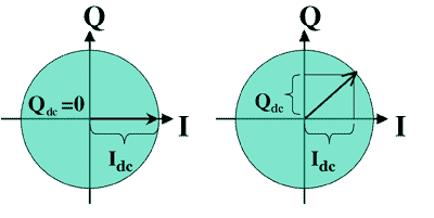
Fig. 2. Unmodulated (a) and modulated (b) carrier. The positive
I axis is arbitrarily chosen to represent 0 degrees relative to the
unmodulated carrier. In part (a), since the plot of the modulated
carrier is relative to the unmodulated carrier, an unmodulated carrier
appears as a fixed vector along the positive I axis. In part
(b), a modulated carrier at the same frequency as the unmodulated
carrier but offset by 45 degrees appears as a fixed vector at 45 degrees.
To produce the carrier in Fig. 2b, equal dc values would be required
at the I and Q modulator inputs. Assuming unity gain in the modulator,
to produce a carrier of unity amplitude at 45 degrees, the I and
Q inputs must both be dc values of Qdc = Idc
= +0.707.
The baseband inputs (those producing the information), must obviously
vary over time, creating a difference between the modulated and
unmodulated carriers. The modulator block diagram is shown below.
The signal first goes through an A/D converter, is compressed, checked
for errors and encoded, then sent through a filter to the IF and
RF mixers:

Fig 3. IQ Modulator and transmitter chain. Baseband
signal appears at left. Block "A" to the right of the
A/D does compression and error-correction.
SIMULATIONS
This Java applet looks at an I/Q modulator by plotting vectors
(phasors), waveforms, and symbols on the I/Q plane. (See explanations
below the simulation.)
|
